TR1 Transceiver
Part Number: 10064
Product Overview
The TR1 Transceiver bridges wireless ANURA vibration sensors to your monitoring and analysis applications over TCP/IP. Through the ANURA Transceiver API, your application software can discover, configure, and communicate directly with sensors. The TR1 also automatically maintains precise time synchronization across all connected sensors and, in multi-transceiver deployments, synchronizes time with other TR1 units via PTP.
Package Contents
Part Number: 10064

Part Number: 40008
Part Number: 40007

Part Number: 40006
Network Requirements
The TR1 operates in standard Ethernet networks. Key requirements:
Power: Either of
IEEE 802.3af-compliant PoE switch, or
IEEE 802.3af-compliant PoE injector
DHCP: DHCP server for automatic IP address assignment
For systems with multiple TR1 devices, all units must be on the same Layer-2 network segment to enable automatic PTP time synchronization.
Note
The TR1 uses Layer-2 PTP multicast packets for time synchronization between multiple transceivers. Some managed switches block this traffic via IGMP snooping or multicast filtering. Consult your switch documentation for PTP/IEEE 1588 compatibility or use a simple unmanaged switch (which typically works without configuration.)
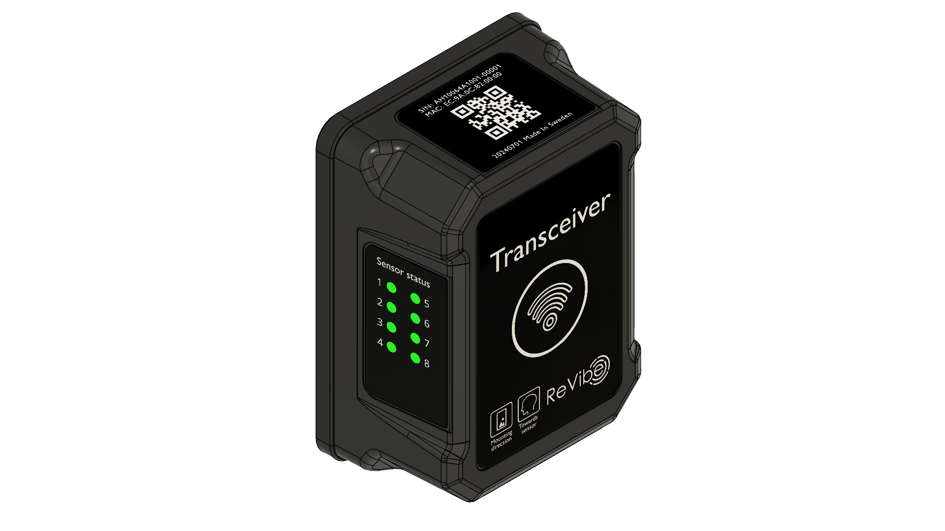
Hardware Overview
Ethernet Port
The etherCON® CAT6A port provides both network connectivity and PoE power. Standard RJ45 Ethernet cables are compatible, but for IP65 ingress protection and full warranty coverage, use ReVibe official cables.
Sensor Status LEDs
LED Color |
Status |
|---|---|
Blue |
Connection established, protocol initialization in progress |
Green |
Connected and fully operational |
Green (blinking) |
Active data transmission to/from sensor |
Orange (all 8) |
Device reset in progress |
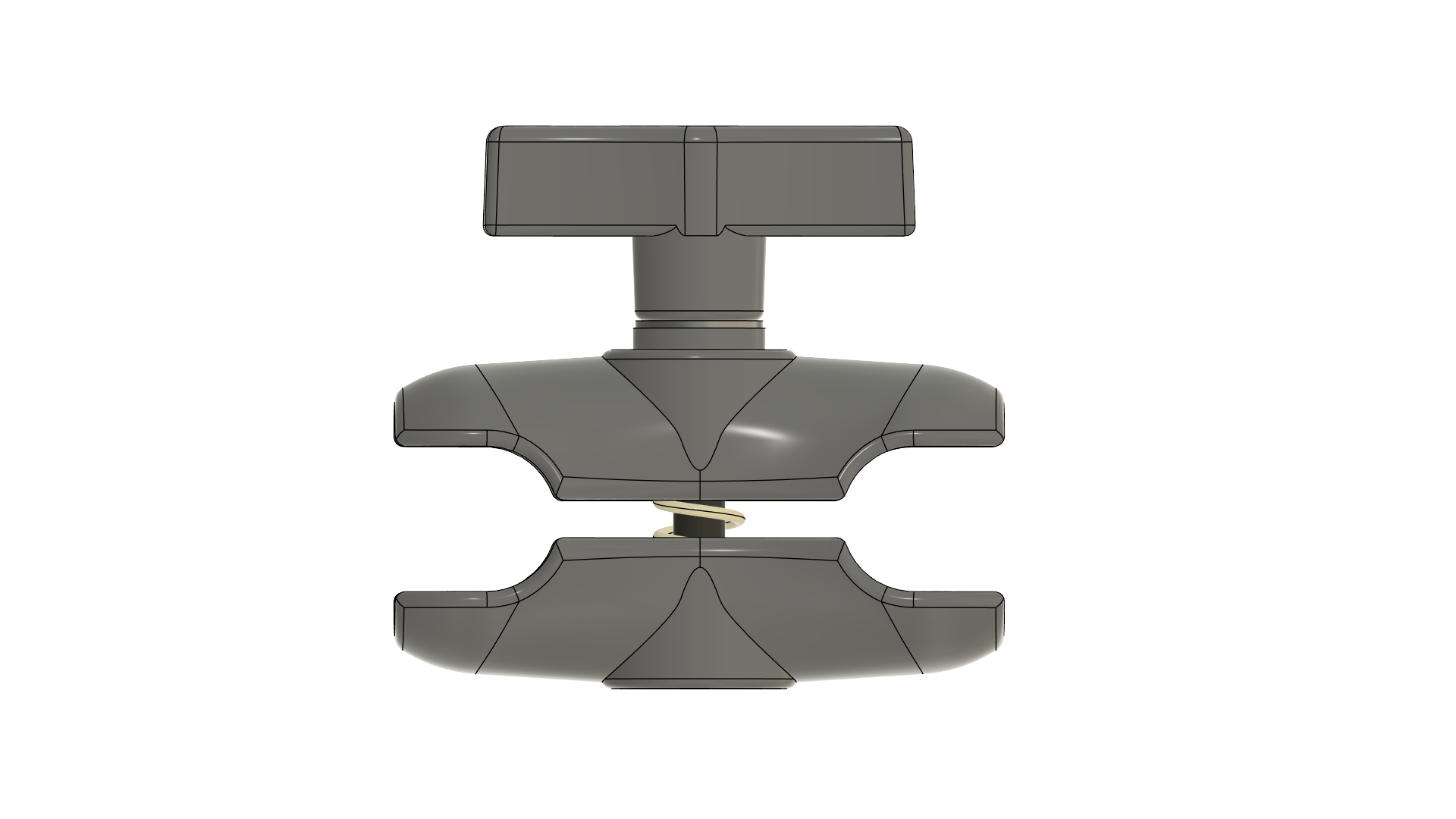
Ball Mount
The TR1 ships with a 1-inch mounting ball pre-assembled to the AMPS 4-hole mounting pattern on the rear panel. The ball mount enables use with a wide variety of mounting arms and brackets.
Configuration
The TR1 does not store configuration in persistent memory—it must be configured after each power cycle via the ANURA Transceiver API. Most configuration is automatic (IP address via DHCP, PTP master selection via best master clock algorithm), but your application must provide the assigned nodes list: the Bluetooth Low Energy addresses of sensor nodes the TR1 should connect to.
Modifying the assigned nodes list does not interrupt TR1 operation. When a node is removed from the list, it will be disconnected while other connections remain active. The TR1 automatically attempts to connect to all assigned nodes and maintains those connections.
Theory of Operation
The TR1 operates as a transparent bridge between your application and wireless sensor nodes. The typical workflow is:
Discovery: Your application discovers TR1 devices on the network via mDNS
Connection: Application connects to the TR1’s ANURA Transceiver API
Configuration: Application provides the list of assigned sensor nodes (BLE addresses)
Connection Management: TR1 automatically connects to assigned nodes and notifies your application of connection/disconnection events
Sensor Communication: Application communicates directly with sensors through the TR1 using AVSS bridge facilities
Connection Management
The TR1 continuously monitors connections to assigned nodes:
Automatically reconnects to nodes that disconnect
Reports connection state changes to your application via API notifications
When a sensor node restarts, the TR1 reconnects automatically, but your application must reconfigure the sensor (the sensor loses its configuration on restart)
AVSS Data Flow
When the TR1 connects to a sensor node, it establishes access to the AVSS service and its four GATT characteristics. The TR1 manages the Timesync Config Characteristic automatically to maintain time synchronization. The remaining three characteristics are exposed to your application through the AVSS bridge features of the Transceiver API:
Report Characteristic: Notifications from the sensor are forwarded as asynchronous API notifications to your application
Control Point Characteristic: The TR1 provides synchronous request/response access via an API method—the underlying BLE Write/Indicate exchange is handled transparently as a single RPC call
Program Characteristic: Used for sensor firmware updates (DFU). Your application can write firmware data to this characteristic, and notifications from the sensor during the update process are forwarded as API notifications
Time Synchronization
The TR1 implements a hierarchical time synchronization architecture to ensure precise, coordinated measurements across all sensors.
TR1-to-TR1 Synchronization (PTP)
In multi-transceiver deployments, all TR1 devices automatically synchronize their internal clocks using IEEE 1588 Precision Time Protocol (PTP). One TR1 is automatically selected as the master clock using the best master clock algorithm, and all other TR1 devices continuously adjust their clocks to follow the master. This synchronization maintains a typical clock offset of less than 5 μs between TR1 units and happens entirely automatically without any application involvement.
TR1-to-Sensor Synchronization
Each TR1 acts as a time synchronization master for its connected sensor nodes. After connecting to a sensor, the TR1 automatically configures the sensor’s time synchronization to follow the TR1’s clock using the proprietary ANURA Timesync Protocol. This hierarchical approach ensures all sensors across all TR1 devices share a common time base, regardless of which transceiver they’re connected to.
Measurement Timestamps
The synchronized sensor clocks enable precise, coordinated measurements across the entire sensor network. All sensor measurement timestamps use the synchronized time base, allowing measurements from different sensors to be accurately correlated in time. Periodic acceleration data measurement windows are synchronized, ensuring that data collection happens simultaneously across all sensors when needed.
Note
While sensor clocks are synchronized to within a few microseconds, the start timestamps of measurement windows from different sensors may differ by up to one sample interval (hundreds to thousands of microseconds). This is expected behavior—the system makes a best effort to align data measurement windows, but perfect alignment is not guaranteed.
Setting Time
Your application can manually set the TR1’s internal clock via the API when needed for initial setup or when operating without PTP synchronization. In most deployments with PTP, manual time setting is unnecessary—the TR1 units synchronize automatically.
Warning
Setting the time introduces a discontinuity in the synchronized time base of both the TR1 and its connected sensors. Use this operation sparingly and avoid calling it after sensors have begun taking measurements.
ANURA Transceiver API
The TR1 exposes all functionality through the ANURA Transceiver API, available on TCP port 7645. The API is built on a CBOR-RPC protocol providing both request/response operations and asynchronous notifications.
Key Capabilities:
Device Management: Configure assigned nodes, query device status
Connection Monitoring: Receive real-time notifications of sensor connections/disconnections
AVSS Bridge: Transparent proxy for communicating directly with sensor AVSS services
Time Management: Set time, query synchronization status
Network Information: Query IP address, hostname, and network configuration
For complete API documentation, see ANURA Transceiver API.
mDNS / Zeroconf
Each TR1 advertises a unique hostname via mDNS based on its network MAC address. The hostname follows the format anura- followed by the MAC address in lowercase hexadecimal (without colons or dashes).
Example: A TR1 with MAC address EC:9A:0C:B2:00:18 advertises the hostname anura-ec9a0cb20018.local
Service Discovery
The TR1 also advertises an mDNS service record (_revibe-anura._tcp) that allows applications to discover all TR1 devices on the network with a single query. This is useful for automatic discovery of multiple transceivers.
Example: On a Linux system with Avahi the following command discovers all TR1 devices on the network.
avahi-browse -r _revibe-anura._tcp
Your application can query _revibe-anura._tcp.local to discover all available TR1 transceivers, provided your system supports mDNS (standard on macOS, Linux with Avahi, and Windows 10+).
Connection Watchdog
The TR1 includes a connection watchdog mechanism to ensure reliable operation in production environments. If no active client connection exists on the ANURA Transceiver API (port 7645) for 24 consecutive hours, the TR1 automatically reboots itself.
The watchdog provides automatic recovery by clearing any transient issues that might prevent normal operation.
Specifications
Dimensions |
140 × 98 × 60 mm |
Weight |
560 g |
Networking Interface |
10/100 Ethernet port |
Power Input |
Power over Ethernet (48V), 802.3af |
Maximum Power Consumption |
1.2 W |
Antenna Gain |
6 dBi |
TX Power |
0 dBm |
Maximum Number of Sensors |
8 |
Certifications |
CE, FCC |
Mounting |
AMPS 4-hole pattern (30 × 38 mm) |
Operating Temperature |
-40 °C to +80 °C |
Operating Humidity |
5% to 95% non-condensing |
Ingress Protection |
IP65 |